This is a 180× speed ‘augmented-reality’ meteor camera video feed from 3 December 2019. Sadly, no meteors were caught in this test run of 60× 1-minute exposures; however, the data nevertheless turned out to be very useful. I used it to develop software to fit an alt-az world coordinate system (WCS) together with a lens distortion map to improve the accuracy. I used Python, OpenCV, Astropy and a slightly modified version of the all_sky_phot package. The WCS continues to be valid until the camera is moved when it then needs to be refitted.
Coordinate systems
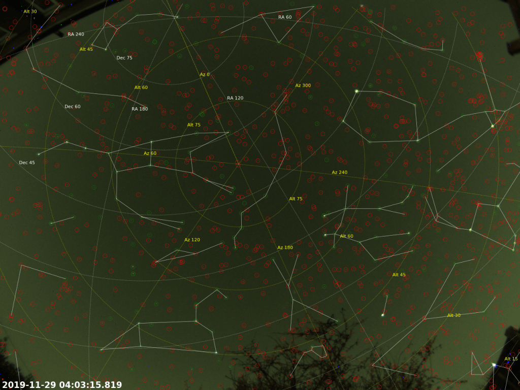
Based on this WCS, I overlaid alt-az and ra-dec grids in yellow and white respectively. The yellow alt-az (i.e. altitude-azimuth) grid fits to the horizon (i.e. altitude = 0°) with its center being the zenith (i.e. altitude = 90°, or the part of the sky that is directly overhead), and with the azimuths of 0°, 90°, 180°, 270° being the compass points N, E, S, W respectively. The white ra-dec (right ascension-declination) grid is the equatorial coordinate system, which is aligned with Earth’s equator (i.e. declination = 90°) and pole or axis of rotation (i.e. declination = 0°). Due to the Earth’s rotation, the stars appear to rotate around the pole and so the white coordinate system rotates around Polaris (‘the North Star’), while the yellow coordinate system remains stationary.
Fisheye lens
A fisheye lens was used to capture a 150° angle of sky. Since the ‘celestial sphere’ is spherical and the camera’s chip is flat, there is a lot of distortion in the images. I initially tried to derive a WCS by plate solving, however the distortion made this extremely difficulty, and although I tried, I was unable to transform the image into the required gnomonic projection. I therefore used a different approach based on fitting an alt-az grid to a number of manually-identified bright stars with a lens distortion map to improve the accuracy to the required level. This video is only the animated result and is not of much value in itself. Instead, the value is in the derived pixel-to-‘celestial sphere’ transformation, which now allows the location of stars and other celestial bodies to be measured based on their position on the camera’s chip.
Constellation lines
In addition to the two grids, and I also overlaid constellation lines. Constellations are groups of stars that form recognisable patterns. They relate to many things such as ancient stories and beliefs, but they are still useful for finding objects and describing locations in the sky.
Stars
Green circles indicate where detected stars coincide with expected star locations (from the Yale Bright Star Catalogue). Red circles indicate expected star locations where a star was not detected (i.e. it was too faint). Inspecting red circles carefully, however, usually reveals a very faint star that can just be seen by eye, but which I couldn’t automatically detect with sufficient certainty.
Motivation
This hardware setup and software development is one of the early steps in a project for meteor detection and trajectory determination. With one camera, the apparent trajectory of a meteor can be measured. With two or more cameras separated by a baseline distance and making simultaneous observations, more useful information can be determined such as an accurate detailed trajectory, including altitude, speed, and in the case of meteorites, an impact site probability map.
Meteors are important to study as they have largely been untouched by anything since the formation of the solar system. The simplest thing to do is to record the number of meteors which seen during a given interval of time. Further value can be added by, for example, recording the time of the observation, the brightness, spectrum, speed and length of the light streak, the part of the sky (or ideally the coordinates of the light streak), or combining multiple observations from different sites to allow range-finding and triangulation.
There are many important questions that can be investigated with such data: For example, are all meteors the remains of disintegrated comets? Do most of them circulate around the sun like planets, or do any come from interstellar space? How fast is the earth growing by accretion of meteoric matter? The paths of satellites and the re-entry of man-made orbital ‘space junk’ can also be monitored with the same techniques.

Augmented-Reality Meteor Camera (3 December 2019)
Frames
- 60× 60-s light frames
- 30× dark frames
Equipment
- Altair GPCAM BASIC Colour camera
- Altair GPCAM Wide Angle Meteor Lens Kit 150 degree FOV
Software
- Sharpcap
- PIPP (to produce the master dark)
- Python with Scipy, OpenCV, Astropy and a slightly-modified version of the all_sky_phot package
Hi. I want to know how did you calibrate and modify the all_sky_phot repo. I am doing a similar task and this would help me so much. Thanks
Thanks for the comment. I can’t remember the fine details as this was a while back. I’ll dig out my old Python code and put it on GitHub.
The general principle was to identify a handful of bright stars across a time-stamped calibration frame, the RA and Dec of which are catalogued, and fit an initial rough world coordinate system (WCS), i.e. sensor-to-world coordinate transformation. I then transformed catalogued star coordinates (RA and Dec) back to the sensor coordinates, and recorded the error between the measured positions and calculated positions. I then used this error to create a distortion table.
I remember I initially tried to use SIPS with polynomial and table corrections – the former worked but not very accurately. The latter did not work using Astropy’s implementation – I reported the issue on the relevant GitHub repo. In the end, I used my own manual tabulated error correction with 2D interpolation, and got pretty good results.
I will upload the code to my GitHub soon…
Regards, Chris
The Python code for this is now available on my GitHub account, here: https://github.com/charvey2718/astro-wcs